Applied Modal & Operating Deflection Shape Analysis
APPLIED MODAL AND OPERATING DEFLECTION SHAPE ANALYSIS
Applied Modal & ODS Analysis
This is a short text area to describe the project. Just write a few words about the purpose, inspiration or success of the project and let the images tell the rest of the story.
Seminar Agenda
Introduction and Course Overview
- Definitions of Experimental Modal & Operating Deflection Shape Analysis
- Terminology of Modal and Operating Deflection Shape Analysis
- Instrument, Transducer & Software Requirements for Modal Analysis
- How Modal Analysis Differs from Operating Deflection Shape Analysis (ODS)
- General Modal and Operating Deflection Shape Analysis Test Methods
- What will Modal Analysis Tell You about the Machine and/or Structure Tested?
Single Channel “Bump" Testing With a Variety of FFT Analyzers
- Single Channel FFT and Time Waveform Measurement
- Recommended Specific Measurement Setups on Various Analyzers
- Importance of Proper Triggering
- Phase Behavior Below, At, & Above Resonance
- Probable Natural Frequencies
- Background Forcing Frequencies
- Corrupted Data - How to Detect & Correct
- Hammer Type and Tip Hardness - Effect on Excited Frequencies
- Limitations of Single Channel Bump
Operating Deflection Shape Analysis (ODS)
- Definition of ODS Analysis & Review of its Applications
- Self-Induced Motions of Machinery
- Defining “How Much” Motion Present
- Defining “Time-Varying” Motions
- Resonant or Non-Resonant Responses
- Animating The Vibrating “Shape”
ODS Rules of Thumb
ODS Demonstrations
- Demonstration of Optimum Techniques Taught
- Use of Instruments from Various Vendors
- Animating ODS Computer Model
- Interpreting ODS Animation Results
- Development of Required Corrective Actions
ODS Case Studies
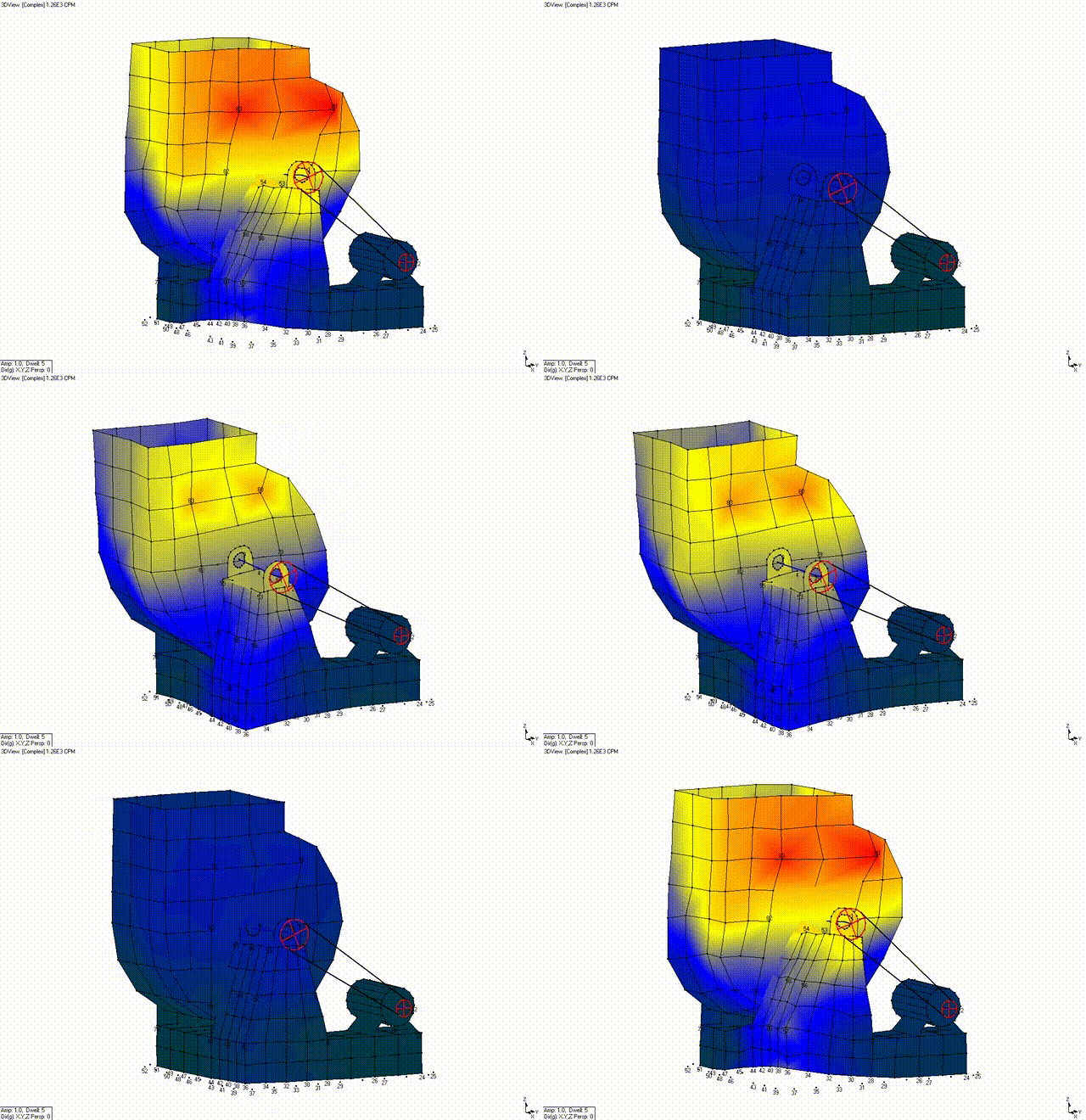
- Excessive Flexure on a Large Scrubber Fan at 3X Fan RPM
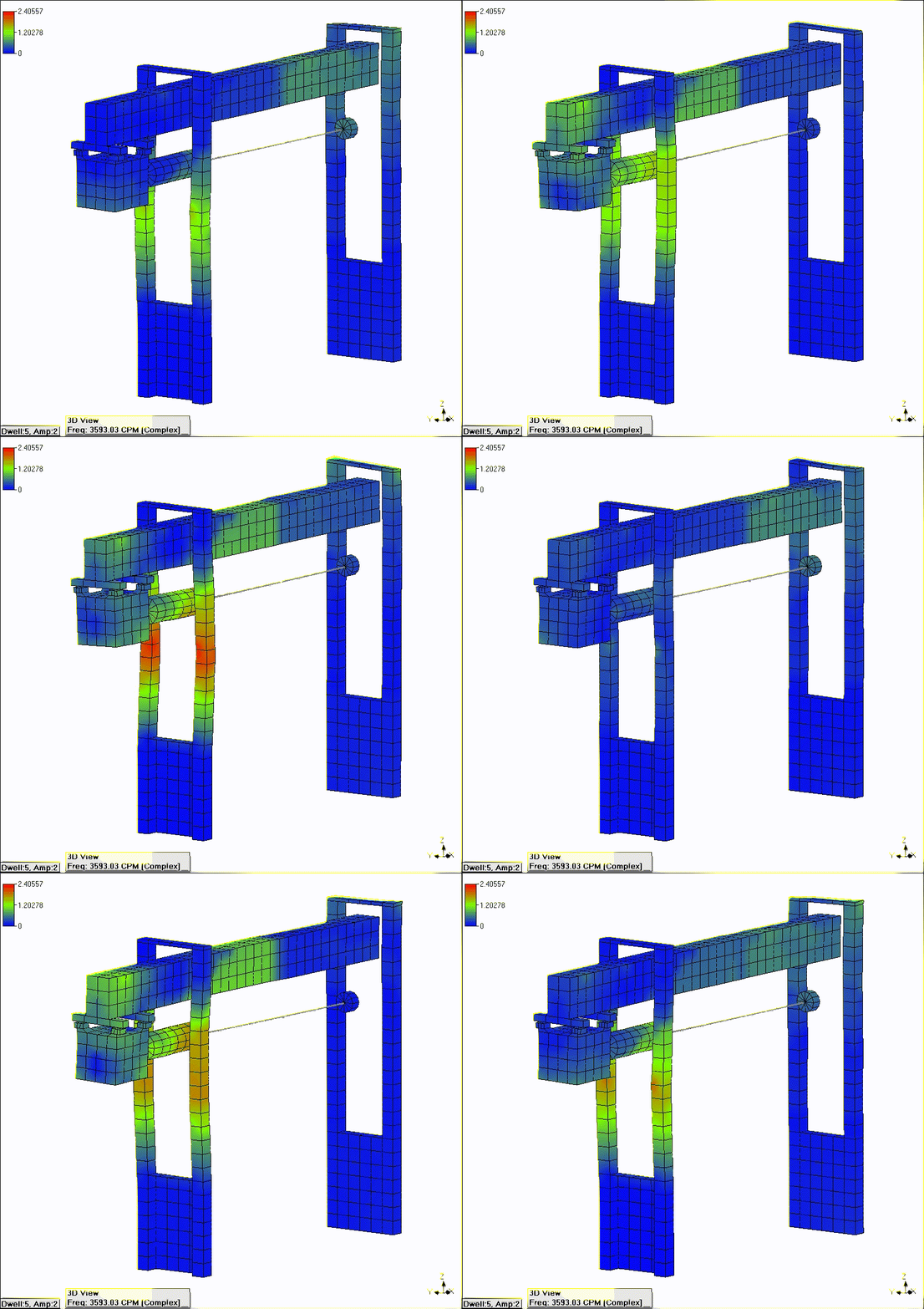
- Structural Weakness & Flexure on a Paper Machine Support Frame
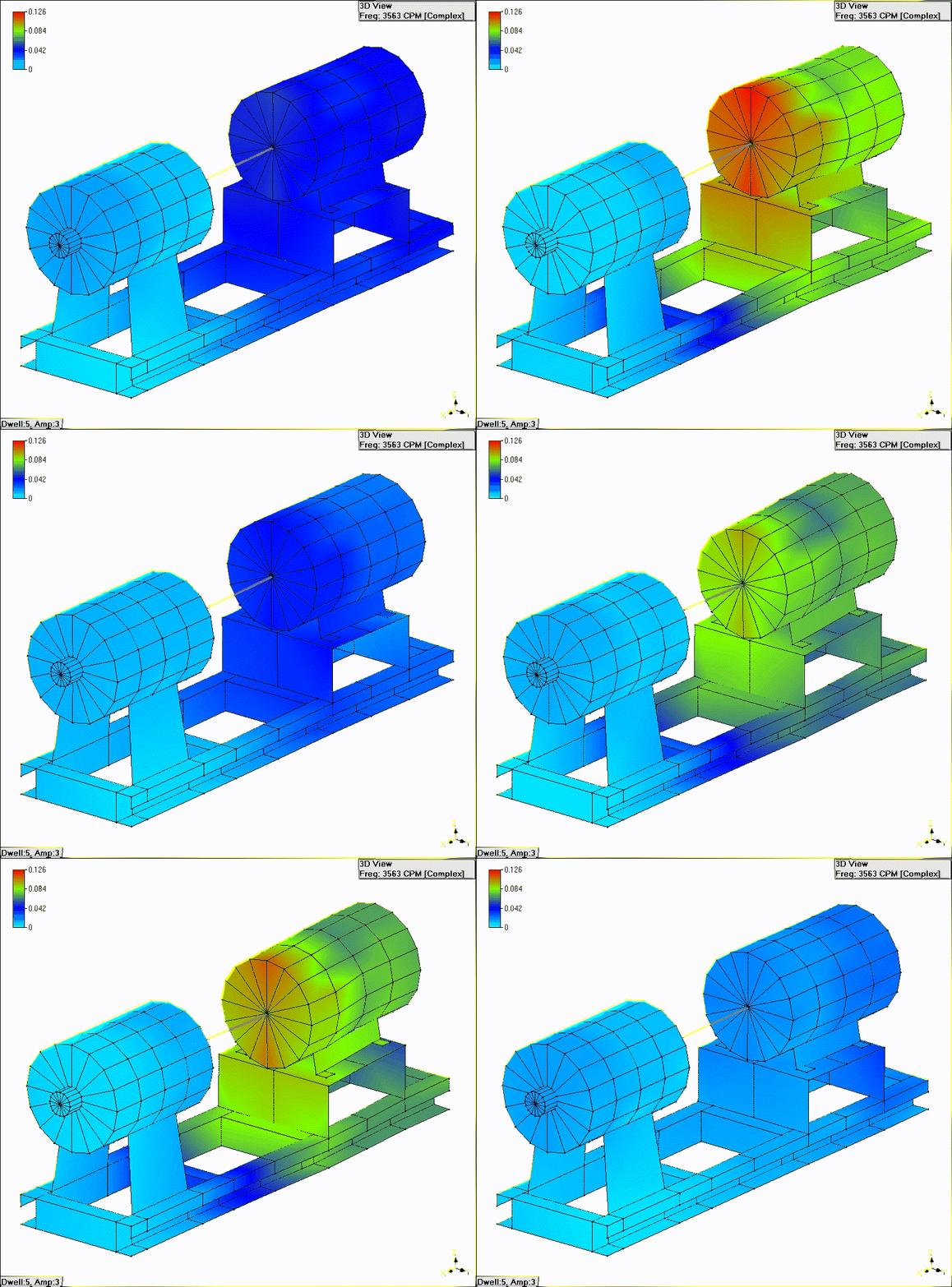
- Misalignment, Excessive Frame Flexure & Ineffective Isolators on a Process Fan
Experimental Modal Analysis (EMA)
- Definition of Modal Analysis & Review of its Applications
- Design Optimization
- Diagnostics on a Variety of Machine Types & Structures
- Troubleshooting Specific Problems
- Confirming When Resonance Exists & What Component is Resonant
- Condition Monitoring Program Enhancement via Modal Analysis
Mode Shapes
- Definition of Mode Shapes & Importance in Resolving Resonance Problems
- Mode Shapes of Simple Machines & Structures
- Mode Shapes of More Complex Machines & Structures
- Mode Shape Types - Rigid Body, Bending & Torsional Modes
- Unique Mode Shape & Damping for Each Excited Natural Frequency
Modal Analysis Requirements
- Overview of Mathematics & Concepts Behind Modal Analysis
- Multi-channel Analyzers - Spectrum Analyzers or Certain Data Collectors
- Modal Analysis Software Available
- Structural Modification Software
- Excitation Instruments - Impulse Force Hammers, Shakers, etc.
Frequency Response Functions (FRF's) & Related Topics
- Definition of FRF's
- Types of FRF's (Dynamic Compliance, Dynamic Stiffness, Mobility, Impedance, Accelerance & Effective Mass)
- Choice of Proper FRF Type for Specific Machine or Structure
- Damping – Real vs. Imaginary
- Use of Real or Imaginary Component for Plotting Mode Shapes
- Coherence Function - Definition and Importance of Coherence on Ensuring Quality Modal Analysis Results
- Cross Channel Phase Measurements
Modal Analysis Rules of Thumb
Modal Analysis Demonstrations on Real Structures & Machines
- Comparison of Results From Instruments Available Today
- Demonstration of Optimum Techniques Taught
- Frequency Response Functions
- Modal Damping
- Mode Shapes
- Interpreting Modal Animation Results
- Development of Required Corrective Actions
Modal Analysis Case Studies
- Turbine Foundation & Bearing Pedestal Resonances Driving an ID Fan
- Detection of Cracks on a Large Gearbox due to Operation Near Resonance
- Resonance Detection on the Frame of a Belt-Driven Blower
- Resonance on a Paper Machine Slitter Frame
